Control Memory
The control memory address register specifies the address of the micro-instruction, and the control data register holds the micro-instruction read from memory. The control memory is assumed to be a ROM (Read Only Memory), which stores all control information.
The next address generator is sometimes called a micro-programed sequencer, as it determines the address sequence that is read from control memory.
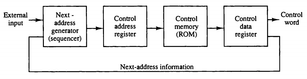
The micro-instruction contains a control word that specifies one or more micro-operations for the data processor.
The address sequencing capabilities required in a control memory are:
- Incrementing of the control address register.
- Unconditional branch or conditional branch, depending on status bit conditions.
- A mapping process from the bits of the instruction to an address for control memory.
- A facility for subroutine call and return.
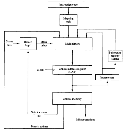
The next figure shows a block diagram of a control memory and the associated hardware needed for selecting the next micro-instruction address.
Micro-instruction Format
The following figure shows the micro-instruction format for the control memory.
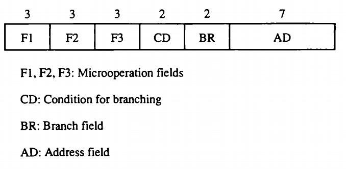
The fields are:
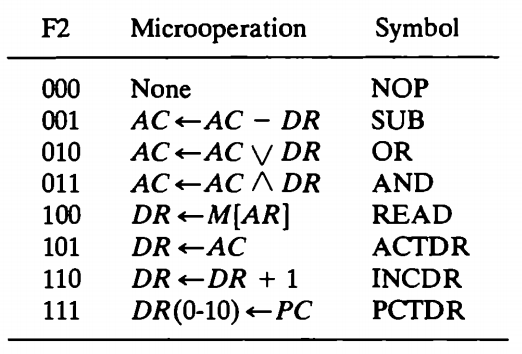
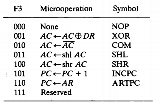
- F1, F2, and F3: Microoperation fields.
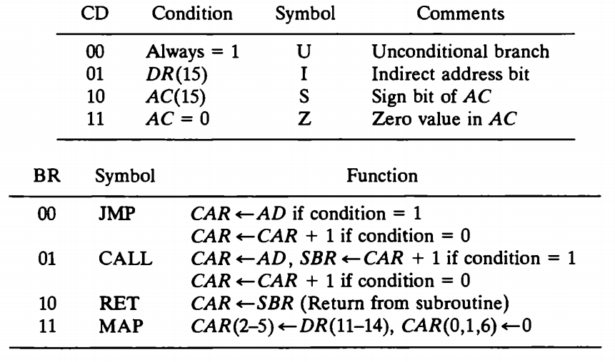
- CD: Selects the status bit conditions.
- BR: Type of the branch to be used.
- AD: Contains the branch address.
The address field is 7-bits as the control memory has 128 words. The micro-operations are subdivided into three fields bits each. The three bits in each field are encoded to specify seven distinct micro-operations which are listed in the following four figures.
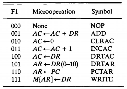
All transfer-type micro-operations symbols use five letters. The first two letters designate the source register, the third letter is always a T, and the last two letters designate the destination register.
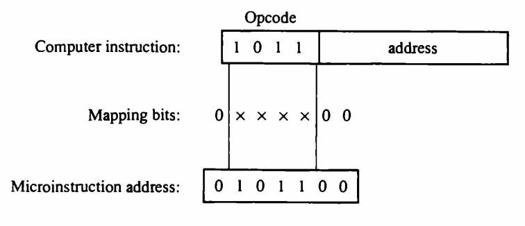
Operations Code Mapping
A special type of branch exists when a micro-instruction specifies a branch to the first word in control memory where a microprogram routine for an instruction is located. The status bits for this type of branch are the bits in the operation code part of the instruction.
The mapping consists of placing a 0 in the most significant bit of the address, transferring the four operation code bits, and clearing the two least significant bits of the control address register.